


REGALIS Fusion is an engineering software solution that supports CPS (Cyber-Physical Systems) by validating real component scan data through virtual manufacturing processes and feeding the results back into actual production.
By applying digital analysis results from the cyber environment directly to the shop floor, it enhances design accuracy, accelerates decision-making, and reduces prototyping costs.
- Predict deformation caused by welding fixture clamping and spot welding
- Virtually validate and optimize the appropriate manufacturing process
- Validate inspection requirements before creating dedicated fixtures
- Replace dedicated fixtures with universal fixtures and virtual clamping
- Convert nominal CAD models into as-built component models using 3D scan data
※REGALIS Fusion requires ALTAIR HyperMesh and OptiStruct to operate
Solve Sheet Metal Measurement Challenges — Virtual CF
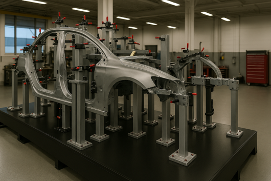
The fundamental challenge in measuring sheet-metal components and similar parts is the difficulty of maintaining a stable shape during inspection.
As a result, dedicated fixtures specific to each part are typically required to reproduce the actual installation posture for accurate measurement. However, producing these fixtures and ensuring their accuracy involves significant cost and complexity.
Virtual CF solves these challenges by combining advanced measurement technology with simulation-based virtual fixturing.
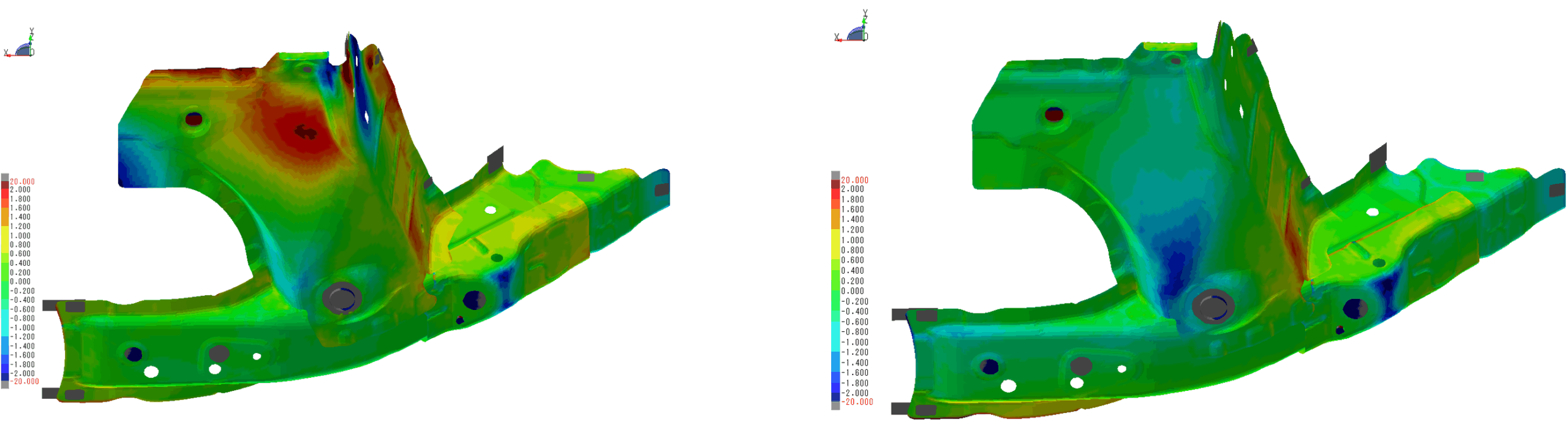
Comparison Between Physical Inspection Fixture Results and Virtual CF Prediction Results

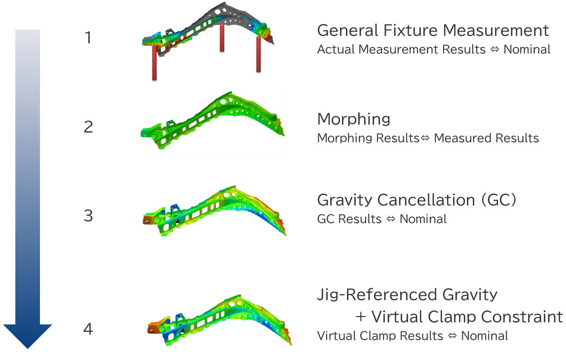
From Inspection Fixtures to Real Parts — Virtual CF Process
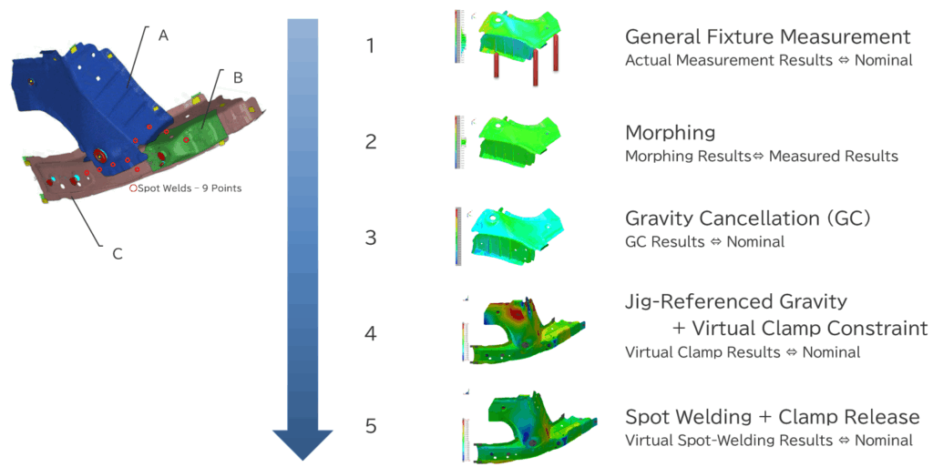
In the Virtual CF process, the actual part is digitally reconstructed in a virtual environment, and the measurement and analysis results are fed back into the real manufacturing process.
Based on the principles of CPS (Cyber-Physical Systems), this workflow streamlines fixture design and validation. The diagram below illustrates this process.
From Gravity Compensation to Virtual Clamping
This section introduces the process from gravity compensation to virtual clamping through diagrams and video.
By correcting deformation caused by the part’s own weight and reproducing the actual mounting condition in a virtual environment, it enables highly accurate measurement and reliable process validation.
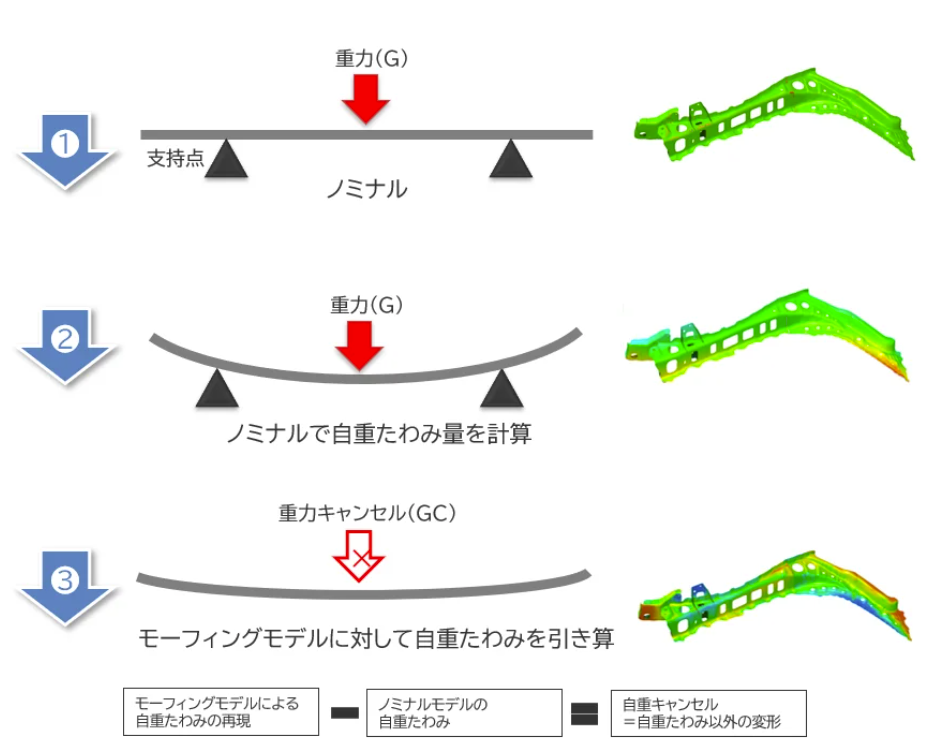
The diagram below conceptually illustrates the analysis workflow from gravity compensation to virtual clamping.
It shows, step by step, how the part is corrected and virtually constrained throughout the process
Please take a look at how the analysis is performed using actual measurement data.
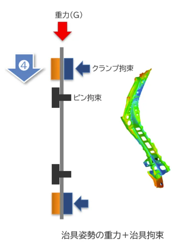
By applying virtual clamping after gravity compensation, the system accurately reproduces the real mounting posture and deformation behavior of the physical part.
Application Examples — Virtual CF
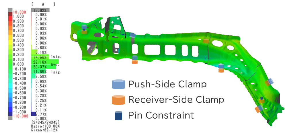
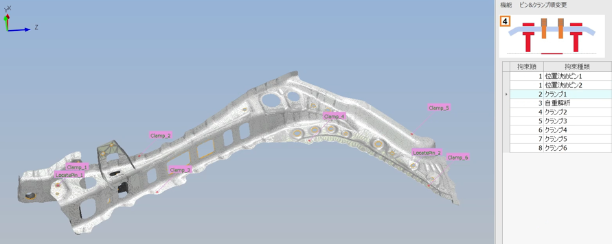
Optimization of Fixture Clamping Plans
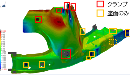
In Virtual CF, clamping plans for inspection fixtures can be evaluated in a virtual environment.
The system analyzes which reference points to use and in what sequence the clamps should be applied to minimize gravitational deflection, allowing you to verify optimal measurement conditions in advance.
In clamp design, friction and operational procedures—such as the clamping sequence—are often not fully taken into account, which can lead to low reproducibility in the results.
With Virtual CF, clamping positions, methods, and sequences can be simulated, enabling the design of highly reproducible measurement plans.
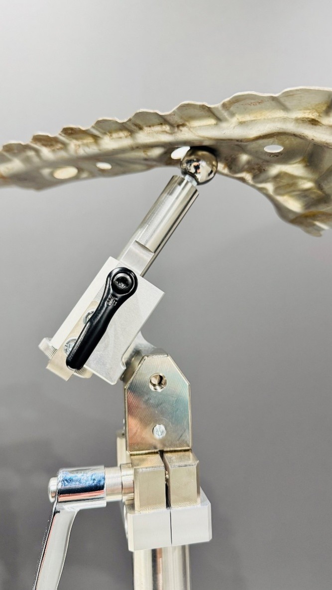
Dedicated to Universal Fixtures with Virtual Clamping
It is possible to perform measurements without dedicated fixtures by combining universal fixtures with virtual clamping technology.
This approach reduces the cost and lead time associated with fixture production while minimizing storage and maintenance burdens.
Dedicated fixtures not only incur production costs and long lead times but also require space for storage and effort for maintenance.Additionally, clamping accuracy can vary, leading to operator-dependent errors.
With Virtual CF, combining flexible measurements using universal fixtures with virtual clamping enables a measurement process that does not rely on dedicated fixtures.
Part-specific dedicated fixtures
Universal fixtures
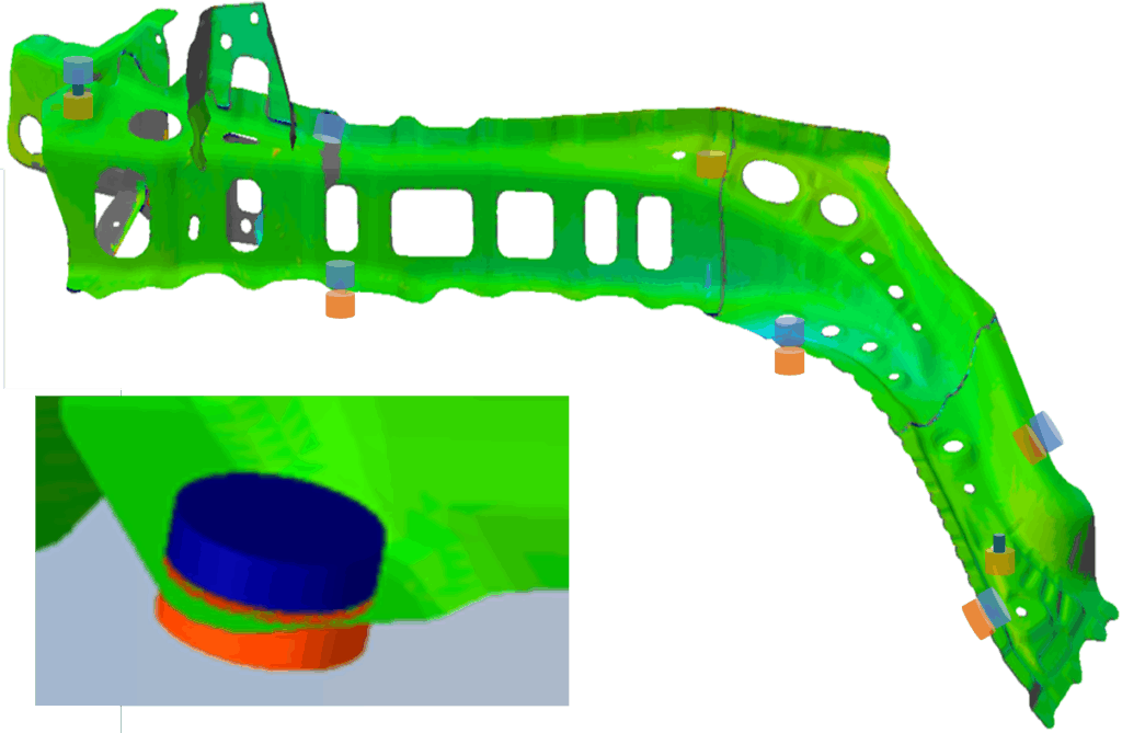
Virtual clamping
Visualizing Non-Gravity Deformation Factors
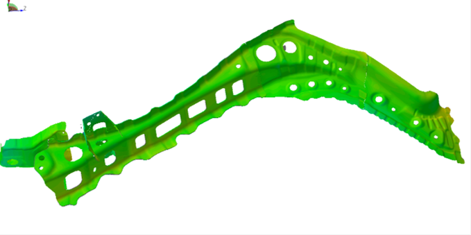
The “Gravity Cancellation” function in Virtual CF clearly visualizes the inherent deformation characteristics of parts. By eliminating the effects of self-weight, it allows you to identify the true deformation factors caused by processes such as forming.
In actual parts, deformation results from a combination of gravitational deflection and other factors, such as forming-induced stresses.
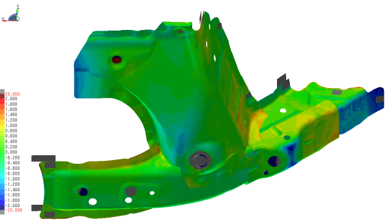
By applying gravity compensation, the theoretical deformation due to the part’s own weight is subtracted, allowing the extraction and evaluation of only the part-specific forming characteristics.
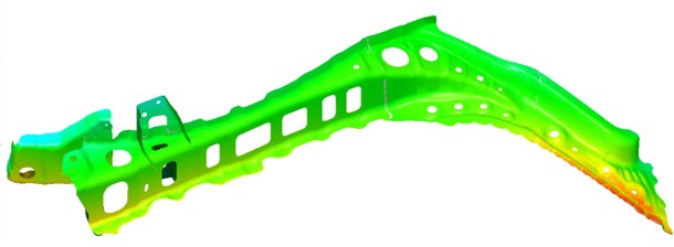
Theoretical gravitational deformation
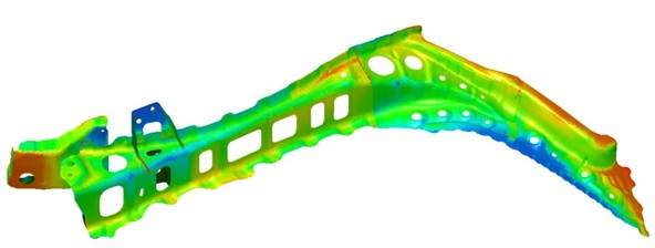
Deformation excluding gravitational deflection
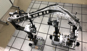
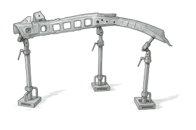
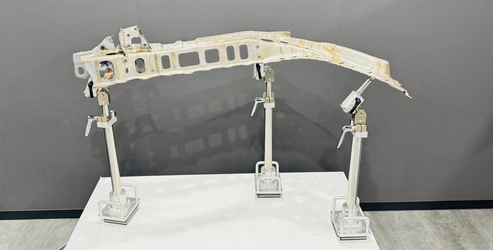
Universal Fixture Inspection Using Simple Point Support
Measurements are performed using simple three-point support, which then serve as the basis for subsequent digital analysis.
Spot Welding Simulation on As-Built Geometry ― Digital Assembly
Identifying defect causes in spot welding is challenging due to factors like fixture adjustments and welding sequences.
Digital Assembly uses actual measurement data and simulation to reproduce as-built geometry and deformations, enabling quick and accurate root cause analysis and corrective planning.
Increased Physical Trial and Error

Fast & Accurate Condition Optimization
Virtual Spot Welding Feedback — Digital Assembly
You can explore typical challenges in manufacturing, such as dimensional deformation and clamping inconsistencies, through REGALIS Fusion application examples.
By performing pre-validation in a virtual environment, unnecessary prototypes and rework are reduced, enabling more efficient and highly accurate process design.
Application Examples — Digital Assembly
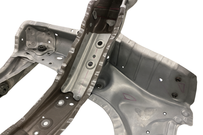
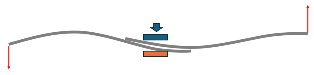
Predict Welding Deformation for Optimal Process Design
During welding fixture clamping, misalignment between parts can occur, leading to interference or gaps that cause deformation.
Based on measurement data from actual panels, it is possible to predict panel gap conditions before, during, and after the process. By anticipating deformation caused by spot welding in advance, an appropriate welding process can be designed.
Part Changes Due to Clamping
Gaps at Mating Surfaces Caused by Clamping
Pre-Evaluation of Panel Alignment Before Welding
When evaluating panel alignment using physical fixtures, individual parts may pass inspection, yet interference or gaps can occur when assembled together. Determining which part requires correction is often difficult, making the preparation process time-consuming.
With Digital Assembly, panel alignment between parts can be evaluated without physical fixtures. It enables data-driven decisions on which parts and to what extent adjustments are needed, while also contributing to fixture simplification.
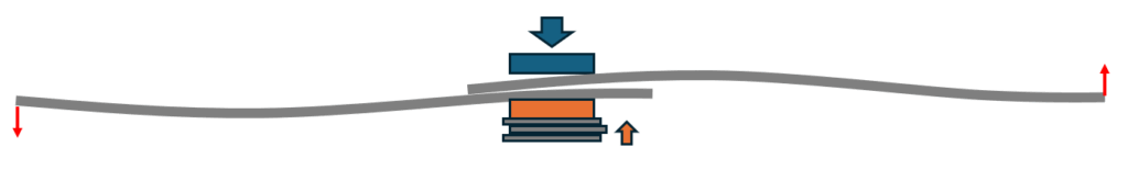
Evaluate the Effect of Clamping Adjustments Using Shims
With numerous clamping points and the difficulty of adjusting estimated values, the process on the shop floor requires a significant amount of time.
With Digital Assembly, shim thickness and adjustment amounts can be virtually modified to evaluate their impact on parts in advance.This enables both more efficient adjustment work and improved accuracy.
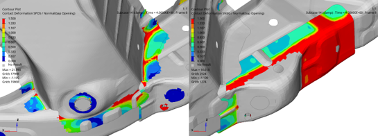
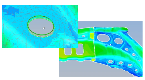
Visualize Stress and Enable Evidence-Based Countermeasures
In conventional inspections, it was possible to tell whether parts were in contact, but the magnitude of the forces acting on them—such as compressive or tensile stress—could not be determined.
With Digital Assembly, both deformations and stresses can be visualized, enabling evidence-based process design and effective corrective planning. This allows the development of optimal process plans, such as distributing stress to avoid concentration, not just controlling deformation within the process.
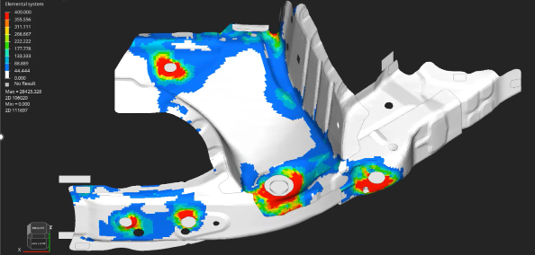
Fixture Setup Stress (Before Clamping)
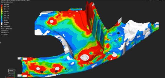
Stress During Clamping and Spot Welding
Evaluation Examples of Digital Assembly Applicable in Manufacturing
Through process reproduction simulations using Digital Assembly, issues such as panel gaps and stress that occur on the manufacturing floor can be visualized.
Analysis results based on actual measurement data are used as evidence to support process improvements and ensure quality stability.
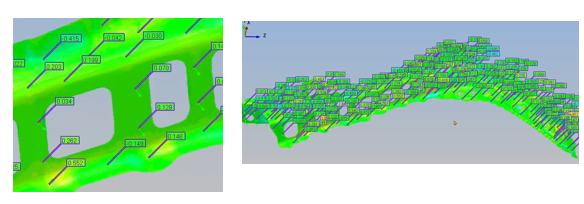
Examples of Deformation and Panel Gap Evaluation
Parts are placed on the welding fixture, and the entire process—from clamping and welding to release—is visualized.
The deformation and panel gap conditions can be quantitatively evaluated.
- Place parts on the welding fixture
- Clamp the parts
- Perform spot welding
- Release the clamps
Gap: 0 to +1.5 mm
Examples of Stress Evaluation
Through a similar process, not only deformations but also stress distributions are analyzed.
Forces and strains within the process are visualized, providing valuable insights for design-stage optimization.
- Place parts on the welding fixture
- Clamp the parts
- Perform spot welding
- Release the clamps
Von Mises Stress: 0–400 MPa
Accurate As-Built Geometry — Morphing
Morphing is a technology that smoothly transforms one shape into another.
Using scan data, it automatically deforms a nominal model to match the as-built geometry, enhancing the accuracy of analysis and process simulations.
Gap Between CAD Model and Actual Part Due to Springback
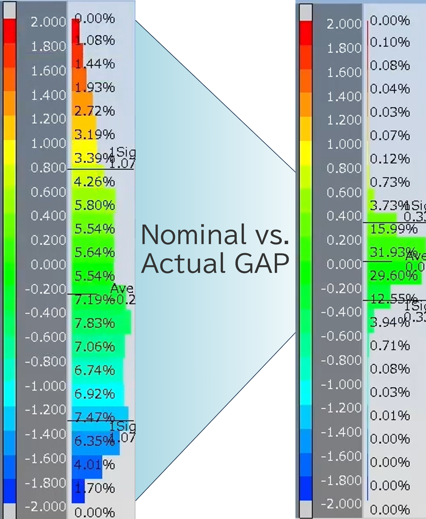
±2 mm or More ±0.2~0.3mm
Gap-Free Model
Challenges and Solutions in Morphing
The automatic morphing feature of REGALIS Fusion automatically detects errors in edges and surfaces of the input data, transforming the nominal analysis model to match the as-built geometry without manual intervention. It addresses traditional challenges almost entirely automatically, significantly reducing labor and processing time.
The automatic morphing feature of REGALIS Fusion automatically detects errors in edges and surfaces from measurement data and deforms the nominal analysis model to match the as-built geometry. It handles traditional challenges almost entirely automatically, greatly reducing labor and processing time.
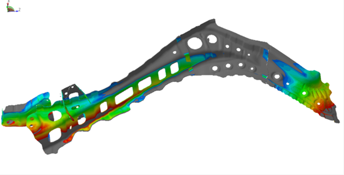
High-Precision and Efficient Morphing
Using measurement data and the analysis model, the as-built geometry is automatically reproduced and deformations are tracked.
With the morphing feature of REGALIS Fusion, high-precision shape analysis can be performed efficiently without relying on manual operations.
Observe the accuracy and reproducibility through actual measurement data analysis examples.
High-Precision Edge Morphing
The outer and inner edges of the analysis model are extracted from measurement data and fitted with high precision to the acquired edges.
Even in areas without measurement data, the model smoothly follows the geometry, maintaining continuous and accurate shapes.
Handle Morphing for Error Reduction
By specifying constraint points (handles), fitting is performed with a target accuracy of ±0.3 mm. Even in areas where measurement is not possible, the geometry is naturally interpolated, reproducing an analysis model that closely matches the actual part.
Experience REGALIS Fusion – Transform Your Manufacturing Floor
REGALIS Fusion leverages CPS to connect design, manufacturing, and verification, helping reduce prototyping and improve shop floor quality.
Explore real-world cases, process flows, and features in our catalog.
Download the catalog or contact us to learn more.